It's fairly simple. It comes from the Interrupts site of the Code Project, the author being Dave Auld, who also wrote both code sections, & provides a really good introduction to interrupts.
Arduino's Reference to attachInterrupts is less comprehensive but gives all the necessary info.
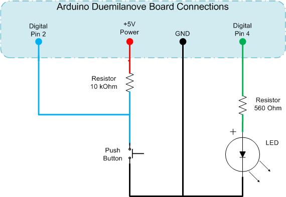
I had to use a 150Ohm resistor in place of a push-switch (which i couldn't find for some reason - i DO have one.. somewhere..). It worked nicely thank-you!
I connected one end of the resistor to Digital Pin 2 on my little breadboard, & touched the other end to GND - in this case the grounded lead of the LED, which promptly turned OFF :-) & back ON again when i released the 150Ohm resistor from contact..
..as expected!
/*
* Project: Interrupts_part_A_621task31
* Author: DaveAuld, tidied (not much! :-) ) by Jane-Maree Howard
* Date: 23 Feb 2010
* Platform: Arduino 22
* Purpose: To demonstrate a simple non-interrupt LED-switch
* Operation: Description:
* "Set up the Arduino as per the schematic
* and upload the code below to the microprocessor.
* Here you read the value of an input,
* do a conditional comparison, run some lengthy routine and repeat.
* This will give unpredictable outputs on the LED
* due to the lengthy process being at an undetermined point
* in relation to when the input button is triggered.
* Sometimes the LED will change state immediately,
* other times nothing happens, and then
* sometimes you need to hold the button for a while
* for the state changed to be recognised.
* [This is code PART A in the downloaded source file.]"
* I had to use a 150Ohm resistor because i couldn't find my push-switch!
* It worked fine!
*/
int pbIn = 2; // Digital input on pin 2
int ledOut = 4; // The output LED pin
int state = LOW; // The input state
void setup()
{
// Set up the digital Pin 2 to an Input and Pin 4 to an Output
pinMode(pbIn, INPUT);
pinMode(ledOut, OUTPUT);
}//setup()
void loop()
{
state = digitalRead(pbIn); //Read the button
digitalWrite(ledOut, state); //write the LED state
//Simulate a long running process or complex task
for (int i = 0; i < 100; i++)
{
// do nothing but waste some time
delay(10);
}//for()
}//loop()
//END
.
No comments:
Post a Comment