Thursday, September 22, 2011

Task 31A -- Standard Digital Input and Output - No Interrupts

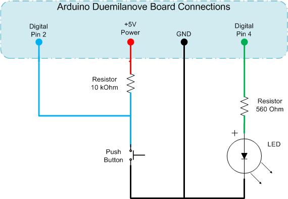
This is the circuit diagram for both parts of the Interrupts task.

It's fairly simple. It comes from the Interrupts site of the Code Project, the author being Dave Auld, who also wrote both code sections, & provides a really good introduction to interrupts.
Arduino's Reference to attachInterrupts is less comprehensive but gives all the necessary info.


I had to use a 150Ohm resistor in place of a push-switch (which i couldn't find for some reason - i DO have one.. somewhere..).  It worked nicely thank-you!
I connected one end of the resistor to Digital Pin 2 on my little breadboard, & touched the other end to GND - in this case the grounded lead of the LED, which promptly turned OFF  :-)  & back ON again when i released the 150Ohm resistor from contact..
..as expected!

/*
 * Project:    Interrupts_part_A_621task31
 * Author:     DaveAuld, tidied (not much! :-) ) by Jane-Maree Howard
 * Date:       23 Feb 2010
 * Platform:   Arduino 22
 * Purpose:    To demonstrate a simple non-interrupt LED-switch
 * Operation:  Description:
 *             "Set up the Arduino as per the schematic
 *              and upload the code below to the microprocessor.
 *              Here you read the value of an input,
 *              do a conditional comparison, run some lengthy routine and repeat.
 *              This will give unpredictable outputs on the LED
 *              due to the lengthy process being at an undetermined point
 *              in relation to when the input button is triggered.
 *              Sometimes the LED will change state immediately,
 *              other times nothing happens, and then
 *              sometimes you need to hold the button for a while
 *              for the state changed to be recognised.
 *              [This is code PART A in the downloaded source file.]"
 *             I had to use a 150Ohm resistor because i couldn't find my push-switch!
 *             It worked fine! 
 */


int pbIn = 2;          // Digital input on pin 2
int ledOut = 4;        // The output LED pin
int state = LOW;       // The input state

void setup()
{
  // Set up the digital Pin 2 to an Input and Pin 4 to an Output
  pinMode(pbIn, INPUT);
  pinMode(ledOut, OUTPUT);
}//setup()

void loop()
{
  state = digitalRead(pbIn);      //Read the button

  digitalWrite(ledOut, state);    //write the LED state

  //Simulate a long running process or complex task
  for (int i = 0; i < 100; i++)
  {
     // do nothing but waste some time
     delay(10);
  }//for()
}//loop()
//END
.

Tuesday, September 20, 2011

Task 30 -- the two Arduino hardware interrupts, & how to use them

References: Arduino.cc     - attachInterrupt()
.                            Dave Auld       - Arduino Interrupts.                       

Sunday, September 18, 2011

TASKS 30-36 -- Automation&Robotics: schedule 6

  • 30.  Write a paragraph about the two hardware interrupts on the Arduino
           and how to use them.
    ~
  • 31.  Carry out the interrupt experiment from the Interrupt post.
           Change the code you find here.
    ~
  • 32.  Find the post on the Triple Axis Accelerometer.
          This is an example of a sensor we have to deal with.
    Find out more information about this sensor and compose a schematic illustrating how you would use an Arduino to real acceleration in three dimensions and display the outputs.
    Your blog output should contain a schematic and code.
    ~
  • 33.  Find a pin-out of the XbeePro.
           Using just Arduino's Tx, Rx ,Gnd and 3.3 VCC draw a quick schematic of how two Arduinos would talk to each other without wires.
    ~
  • 34.  Use the above two tasks to produce a schematic of  a circuit
           that would read the accelerometer 's three axis readings and then output to an Arduino and then broadcast out to another Arduino that would send the data to a serial terminal for saving in a file.
    ~
  • 35.  Write the Arduino code for the sender that reads the accelerometer
           values and sends them via the XbeePro.
    ~
  • 36.   Write the Arduino code for the receiver that's attached to the PC.

    Task 27 -- The Wire Librrary

    27. List the main functions of the Wire library.
           Say what they do with examples.

    ~~~~~~~~~~~~~~~~~~~~~~~~~~~~~~~~~~~~~~~~~~~~~~~~

    Wire Library Functions
    ======================

    1.    begin()
          begin(address)

    Initiates the Wire library and joins I2C bus as master or slave.
    Normally called only once.

    Parameters: address: the 7-bit slave address (optional);
            if not specified, join the bus as a master.
    No returns.
    ~~~~~~~~~~~~~~~~~~~~~~~~~~~~~~~~~~~~~~~~~~~

    2.  requestFrom(address, count)

    Used by master to request bytes from slave device.
    The bytes may then be retrieved with the available() and receive() functions.

    Parameters:    address:  the 7-bit address of device to request bytes from
            quantity: the number of bytes to request
    No returns.
    ~~~~~~~~~~~~~~~~~~~~~~~~~~~~~~~~~~~~~~~~~~~~


    3.  beginTransmission(address)

    Begin transmission to I2C slave device with address given.
    Queue bytes for transmission with send() function.
    Transmit bytes by calling endTransmission().

    Parameters: address: 7-bit address of device to transmit to
    No returns.
    ~~~~~~~~~~~~~~~~~~~~~~~~~~~~~~~~~~~~~~~~~~~~


    4.  endTransmission()

    Ends transmission to slave device begun by beginTransmission()
    Actually transmits the bytes queued by send().

    No parameters.

    Returns: byte, indicating transmission status:

    0   success
    1   data too long to fit in transmit buffer
    2   received NACK on transmit of address
    3   received NACK on transmit of data
    4   other error.
    ~~~~~~~~~~~~~~~~~~~~~~~~~~~~~~~~~~~~~~~~~~~~


    5.  send()

    Sends data from slave device in response to request from master, or
    queues bytes for transmission from master to slave device
    (in-between calls to beginTransmission() and endTransmission()).

    Parameters: value:      a byte to send (byte)
            string:     a string to send (char *)
            data:       an array of data to send (byte *)
            quantity:     the number of bytes of data to transmit (byte)
    No returns.
    ~~~~~~~~~~~~~~~~~~~~~~~~~~~~~~~~~~~~~~~~~~~~

    6.  byte available()

    Returns number of bytes available for retrieval with receive().
    Should be called on master device after call to requestFrom(),
    or on slave inside the onReceive() handler.

    No parameters;
    Returns:  number of bytes available for reading.
    ~~~~~~~~~~~~~~~~~~~~~~~~~~~~~~~~~~~~~~~~~~~~

    7.  byte receive()

    Retrieves byte transmitted from slave device to master
    after call to requestFrom()
             or transmitted from master to slave.

    No parameters;
    Returns:  next byte received.

    ~~~~~~~~~~~~~~~~~~~~~~~~~~~~~~~~~~~~~~~~~~~~~
    8.    onReceive(handler)
    9.    onRequest(handler)

    These are not much used in our projects.

    Note: On most Arduino boards,
                       SDA (data line) is on analog input pin 4, and
                       SCL (clock line) is on analog input pin 5.


    Reference:  http://arduino.cc/en/Reference/Wire
    .

    Friday, September 16, 2011

    Task 24 - DIY TWI protocol using 8-bit data-path

    ..

    TASKS 24-29 -- Automation&Robotics: Schedule 5

    • Tasks

      Please respond to these tasks in your blog using the same reference numbers.
       
    • 24.   Use the example given in class
              to write your own two wire protocol that can deliver 8 bits
      on the data line and use the clock line to indicate valid data.
      Test with a colleague's Arduino and write up your results.
      ~
    • 25.  Same as 24 but this time use a four-bit data path.
      ~
    • 26.  Plan a TWI between two Arduinos.
      Scan a diagram, or illustrate in some other way, how the connections will be
      set up and which is master and which is slave.
      Have a look at http://absences.sofianaudry.com/en/node/10  or at 
      http://arduino.cc/en/Tutorial/MasterWriter
       for some example code.
      ~
    • 27.  List the main functions of the Wire library.
             Say what they do with examples.
      ~
    • 28.  Construct a real TWI between two Arduinos.
             Take a photo and publish your code and any issues you had.
      ~
    • 29.   If I had three Arduinos, is it possible to produce an RS
      ~