Well, to start with, here's some test information. Bit scary.. i had the erroneous impression it'd be next week, but it isn't!
Here's some hardware pics & the ATmega328 datasheet..
..& the pin-mapping between the ATmega328 & the Arduino..
We're getting lotsa questions on this.
Here's a schematic of the Duemilanove..
..& the Uno schematic.
.
Showing posts with label schematic. Show all posts
Showing posts with label schematic. Show all posts
Tuesday, November 15, 2011

Sunday, September 25, 2011
Project 3 -- Minor Project: schematic

The 3 'wriggly' things are Peltier elements (Thermistors)
Project 3 -- Minor Project: Design
My MINOR PROJECT has the following hardware design features:
** 3 thermistors on a wiring loom able to be set up inside my fridge.
** 1 photocell on the same wiring loom.
** A Duemilanove Arduino board,
to poll the 3 temperatures at around 1 minute intervals,
with an interrupt feature involving the photocell
(for when the door is opened - & closed again,
& the software to save to & retrieve the data from the on-board EEPROM.
The whole project can be independently powered through the USB port - i have a USB power source, but a bit of tweaking may enable power to be supplied by a 9v battery (not sure about this).
The software design involves the following:
** Regular polling of the 3 thermistors connected to Analog pins A0, A1, A2.
Their readings are saved to EEPROM
** An interrupt feature triggered by the photocell connected to Analog pin A3.
The interrupt is attached to Digital pin 2,
triggered by the photocell reading rising above a pre-determined 'darkness' threshold.
A LED will be lit & the fact recorded on EEPROM in binary form (1 = open).
** A Serial Monitor connection enabling retrieval of the recorded data on a signal from the serial connection (via SM).
** A software delay enabling the project to be set up & connected to its power source - nothing will happen for about 5 minutes - then the program starts recording data.
** The software delay can be over-ridden by a signal from the SM, when the project is connected to a PC; data retrieval can then begin.
** Data retrieved from the EEPROM is written to the SM, appropriately formatted.
.
** 3 thermistors on a wiring loom able to be set up inside my fridge.
** 1 photocell on the same wiring loom.
** A Duemilanove Arduino board,
to poll the 3 temperatures at around 1 minute intervals,
with an interrupt feature involving the photocell
(for when the door is opened - & closed again,
& the software to save to & retrieve the data from the on-board EEPROM.
The whole project can be independently powered through the USB port - i have a USB power source, but a bit of tweaking may enable power to be supplied by a 9v battery (not sure about this).
The software design involves the following:
** Regular polling of the 3 thermistors connected to Analog pins A0, A1, A2.
Their readings are saved to EEPROM
** An interrupt feature triggered by the photocell connected to Analog pin A3.
The interrupt is attached to Digital pin 2,
triggered by the photocell reading rising above a pre-determined 'darkness' threshold.
A LED will be lit & the fact recorded on EEPROM in binary form (1 = open).
** A Serial Monitor connection enabling retrieval of the recorded data on a signal from the serial connection (via SM).
** A software delay enabling the project to be set up & connected to its power source - nothing will happen for about 5 minutes - then the program starts recording data.
** The software delay can be over-ridden by a signal from the SM, when the project is connected to a PC; data retrieval can then begin.
** Data retrieved from the EEPROM is written to the SM, appropriately formatted.
.
Saturday, September 24, 2011
Task 32 -- the Triple Axis Accelerometer
"Find the post on the Triple Axis Accelerometer.
This is an example of a sensor we have to deal with.
Find out more information about this sensor
and compose a schematic illustrating how you would use an Arduino to (record) real acceleration in
three dimensions and display the outputs.
Your blog output should contain a schematic and code."
Umm, here's my post on the hardware (with pikkie!).
Now we should have a schematic..
(Fritzing is good for drawing schematics!)
Here's the datasheet..
..& a circuit diagram (courtesy of Fritzing) showing how the accelerometer is connected to an Arduino board & external power source (not complicated at all, is it)

This is an example of a sensor we have to deal with.
Find out more information about this sensor
and compose a schematic illustrating how you would use an Arduino to (record) real acceleration in
three dimensions and display the outputs.
Your blog output should contain a schematic and code."
Umm, here's my post on the hardware (with pikkie!).
Now we should have a schematic..
(Fritzing is good for drawing schematics!)
Here's the datasheet..
..& a circuit diagram (courtesy of Fritzing) showing how the accelerometer is connected to an Arduino board & external power source (not complicated at all, is it)


Thursday, September 22, 2011
Task 31B -- Making Use of Interrupts
 ..
..Again the schematic is from the Code Project/Interrupts site.
(I had to use a 150Ohm resistor because i couldn't find my push-switch!
It didn't work quite as well - i should really find that switch! - but i
suspect my wobbly hand had a lot to do with it; i could try 'de-bouncing'
the 'switch', but delay() won't work inside the interrupt-triggered function
(find the switch, stoopid!) )
This time, however, the code makes use of a Hardware Interrupt, as follows:
/*
* Project: Interrupts_part_B_621task31
* Author: DaveAuld, tidied (not much! :-) ) by Jane-Maree Howard
* Date: 23 Feb 2010
* Platform: Arduino 22
* Purpose: To demonstrate a simple interrupt-triggered LED-switch
* Operation: Description:
* "Set up the Arduino as per the schematic
* and upload the code below to the microprocessor.
* We will use the same schematic diagram and
* modify the code to make use of hardware interrupts.
* Now when you upload the code, the LED changes state
* whenever the button is pressed
* even though the code is still running the same long delay
* in the main loop.
* [This is code PART B in the downloaded source file.]"
*/
int pbIn = 0; // Interrupt 0 is on DIGITAL PIN 2!
int ledOut = 4; // The output LED pin
volatile int state = LOW; // The input state toggle
void setup()
{
// Set up the digital pin 2 to an Interrupt and Pin 4 to an Output
pinMode(ledOut, OUTPUT);
//Attach the interrupt to the input pin and monitor for ANY Change
attachInterrupt(pbIn, stateChange, CHANGE);
}//setup()
void loop()
{
//Simulate a long running process or complex task
for (int i = 0; i < 100; i++)
{
// do nothing but waste some time
delay(50); // Jane-Maree increases delay time from 10ms to 50ms
}//for()
}//loop()
void stateChange()
{
state = !state;
digitalWrite(ledOut, state);
}//stateChange()
//END
Task 31A -- Standard Digital Input and Output - No Interrupts
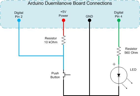
It's fairly simple. It comes from the Interrupts site of the Code Project, the author being Dave Auld, who also wrote both code sections, & provides a really good introduction to interrupts.
Arduino's Reference to attachInterrupts is less comprehensive but gives all the necessary info.
I had to use a 150Ohm resistor in place of a push-switch (which i couldn't find for some reason - i DO have one.. somewhere..). It worked nicely thank-you!
I connected one end of the resistor to Digital Pin 2 on my little breadboard, & touched the other end to GND - in this case the grounded lead of the LED, which promptly turned OFF :-) & back ON again when i released the 150Ohm resistor from contact..
..as expected!
/*
* Project: Interrupts_part_A_621task31
* Author: DaveAuld, tidied (not much! :-) ) by Jane-Maree Howard
* Date: 23 Feb 2010
* Platform: Arduino 22
* Purpose: To demonstrate a simple non-interrupt LED-switch
* Operation: Description:
* "Set up the Arduino as per the schematic
* and upload the code below to the microprocessor.
* Here you read the value of an input,
* do a conditional comparison, run some lengthy routine and repeat.
* This will give unpredictable outputs on the LED
* due to the lengthy process being at an undetermined point
* in relation to when the input button is triggered.
* Sometimes the LED will change state immediately,
* other times nothing happens, and then
* sometimes you need to hold the button for a while
* for the state changed to be recognised.
* [This is code PART A in the downloaded source file.]"
* I had to use a 150Ohm resistor because i couldn't find my push-switch!
* It worked fine!
*/
int pbIn = 2; // Digital input on pin 2
int ledOut = 4; // The output LED pin
int state = LOW; // The input state
void setup()
{
// Set up the digital Pin 2 to an Input and Pin 4 to an Output
pinMode(pbIn, INPUT);
pinMode(ledOut, OUTPUT);
}//setup()
void loop()
{
state = digitalRead(pbIn); //Read the button
digitalWrite(ledOut, state); //write the LED state
//Simulate a long running process or complex task
for (int i = 0; i < 100; i++)
{
// do nothing but waste some time
delay(10);
}//for()
}//loop()
//END
.
Subscribe to:
Posts (Atom)